Key Precautions for Reliable Industrial PCB Design


Essential Precautions in Industrial PCB Design for Optimal Performance and Reliability
In the fast-changing world of industrial electronics, designing Printed Circuit Boards (PCBs) is crucial for making sure devices work well and last long. Industrial environments can be tough, with extreme temperatures and strong electromagnetic interference. To handle these issues, PCB designers need to follow some important rules. This article highlights the main things to consider when designing sturdy and reliable industrial PCBs.
1. Thermal Management
Heat Dissipation:
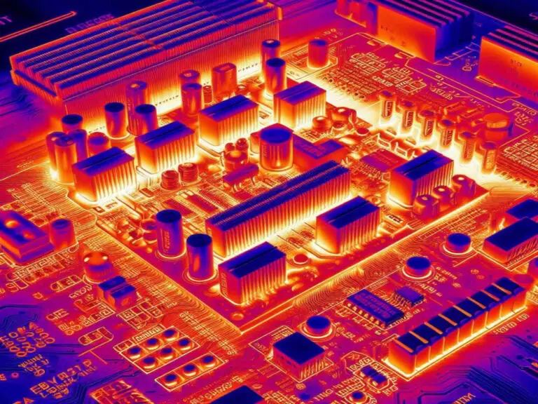
Industrial PCBs frequently contain components that produce a lot of heat. Proper thermal management is essential to avoid overheating, which can cause components to fail early or operate poorly. To control heat, designers can use techniques such as thermal vias, heat-sinks, or thermal pads. Additionally, incorporating sufficient copper pours and employing heat-spreading methods can help ensure effective heat dissipation.
Component Placement:
Proper placement of heat-sensitive components away from heat sources is essential. Additionally, the design should consider the airflow and cooling systems within the final enclosure to ensure that heat is effectively managed.
2. Electrical Performance
Signal Integrity:
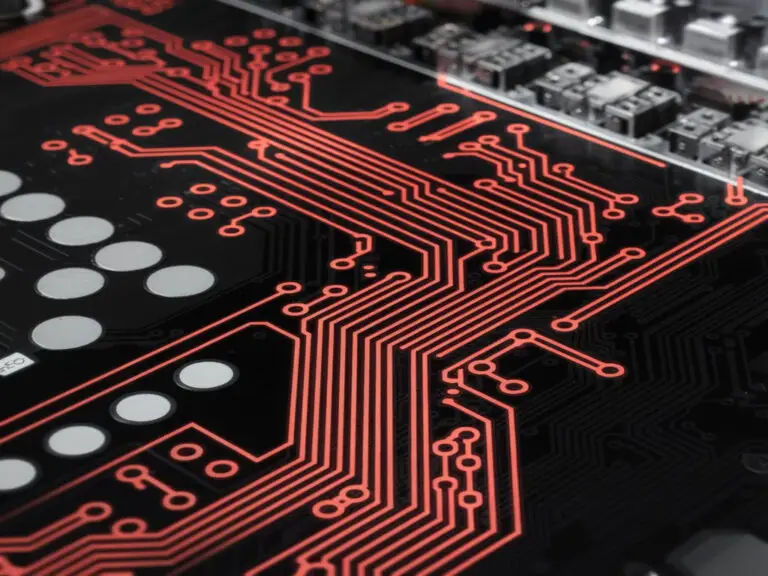
High-speed and delicate signal lines can easily pick up interference and crosstalk. To avoid these issues, designers need to carefully plan how these signals are routed. Using controlled impedance routing techniques is important to keep the signals clear and accurate, especially in high-frequency applications.
Power Distribution:
A strong power distribution network is essential for reliable device operation. Designers should add enough decoupling capacitors and make sure there are low-resistance paths to avoid voltage drops and noise, which can impact circuit performance.
3. Mechanical Considerations
Component Mounting:
Ensuring that components are securely mounted is vital for long-term reliability. Designers must consider mechanical stress and use appropriate pad sizes and anchor points to avoid component displacement or damage during operation.
PCB Size and Shape:
The PCB must be designed to fit within the intended enclosure, with consideration for mounting holes, edge clearances, and other mechanical features. Proper alignment with the enclosure ensures that the PCB can be securely mounted and protected.

4. Design Rules and Standards
Clearances and Spacing:
In industry standards for trace widths, spacing between traces, and component clearances is very important. These rules help prevent short circuits and ensure that the PCB is made accurately and reliably.
Regulatory Compliance:
Industrial PCBs must meet various industry standards and regulations, such as those outlined by the IPC (Institute of Printed Circuits). Compliance with these standards ensures that the PCB meets safety, performance, and quality requirements.
5. Environmental Factors
Moisture and Corrosion Resistance:
Industrial settings can be tough, with moisture, dust, and corrosive materials posing risks. To safeguard the PCB, designers can apply conformal coatings or potting compounds to shield it from these environmental factors.
Temperature Extremes:
Industrial PCBs need to work reliably in a wide temperature range. It’s important to choose components that can handle the expected temperatures and to design with thermal management in mind to ensure long-lasting performance.
6. Manufacturability and Assembly
Design for Assembly (DFA):
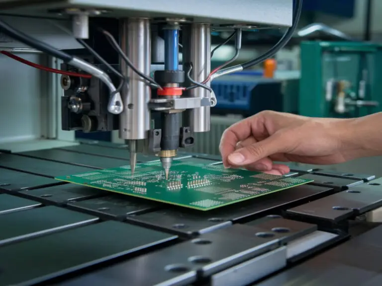
The PCB design should facilitate efficient assembly processes. Clear placement for automated pick-and-place machines and easy access for soldering help reduce assembly time and costs.
Design for Manufacturability (DFM):
The design should avoid complex geometries or features that could be challenging to manufacture. Ensuring that the PCB is manufacturable within cost and quality constraints is essential for a successful product.
7. Testing and Debugging
Test Points:
Incorporating test points for key signals and power rails is essential for effective testing and debugging. These test points make it easier to measure and troubleshoot the circuit during development and maintenance.
Design for Test ability (DFT):
Designing the PCB with test ability in mind is crucial. This approach enables efficient in-circuit testing (ICT) or boundary scan methods, which helps identify and fix problems early in development.
8. Electromagnetic Compatibility (EMC)
Shielding:
To reduce electromagnetic interference (EMI) and radio-frequency interference (RFI), designers can use shielding techniques or incorporate additional PCB layers to contain and minimize interference.
Grounding:
Creating a solid ground plane and using proper grounding techniques are essential for reducing noise and improving signal integrity. A well-planned grounding strategy boosts PCB performance and reliability.
Conclusion
Designing industrial PCBs requires balancing multiple factors to achieve optimal performance and reliability in challenging environments. Addressing aspects like thermal management, electrical performance, mechanical considerations, design standards, environmental conditions, manufacturability, testing, and electromagnetic compatibility is crucial. By carefully considering these elements, designers can create PCBs that excel in industrial applications, offering both functionality and durability.At Ioscape, we are committed to integrating these best practices to ensure that our PCBs meet the highest performance and longevity standards.